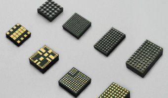


 Integrated Magnetic Power Module
Buck (Step-Down)-Low Voltage
Buck (Step-Down)-Medium Voltage
Boost (Step-Up)
DC-DC Power Modules
Integrated Magnetic Power Module
Buck (Step-Down)-Low Voltage
Buck (Step-Down)-Medium Voltage
Boost (Step-Up)
DC-DC Power Modules
 Magnetically Integrated Power Module (SiP)
Buck (Step-Down)-Multiple Outputs
Buck (Step-Down)
Boost (Step-Up)
Magnetically Integrated Power Module (SiP)
Buck (Step-Down)-Multiple Outputs
Buck (Step-Down)
Boost (Step-Up)
 Customized DC-DC Converters
Tailored Power Modules: Precision Solutions for Your Unique Needs.
Contact Us Today to Discuss Your Project!
DC-DC Power Modules
Customized DC-DC Converters Explore DC-DC Converters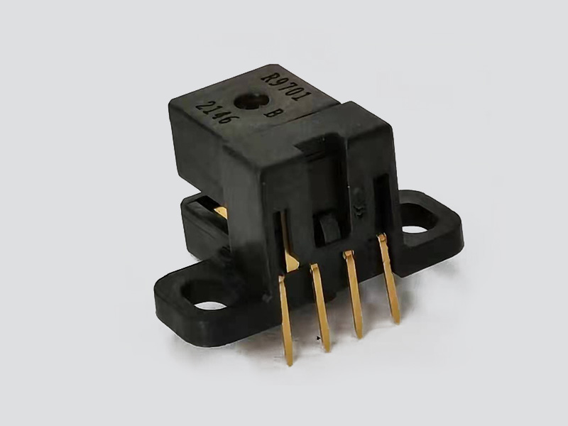
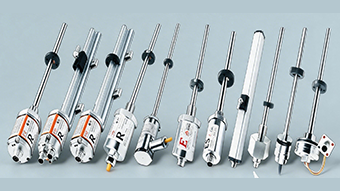
RS970 Series 2 Channel Optical Encoder Module
Details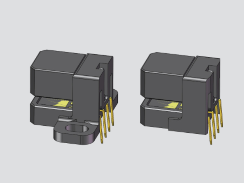
RS972 Optical Encoder Modules
Details
RZ7810 High Resolution Absolute Encoder 23/25 Bit Multi Turn with RS485
Details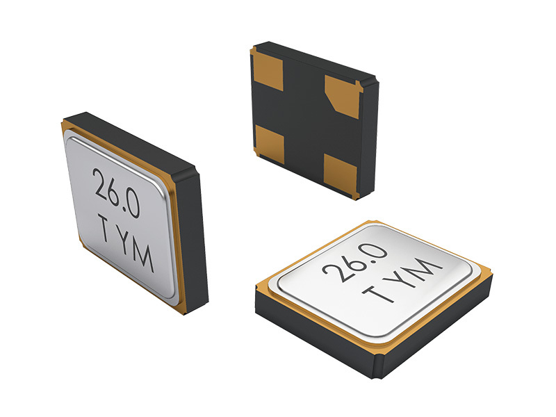
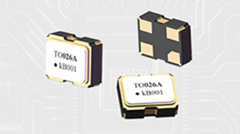
M2016 MHz Crystal SMD
Details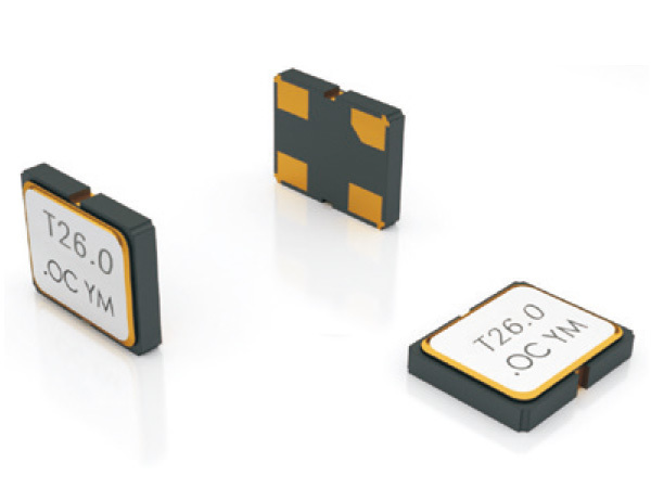
XO2016 SMD Oscillator
Details
TC1612 SMD VCTCXO IoT GPS Oscillator
Details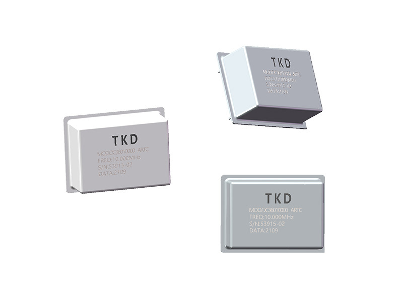
TOC2525 Precision TCXO Crystal Oscillator
Details
RS971 Series 2-Channel Optical Encoder Module
Details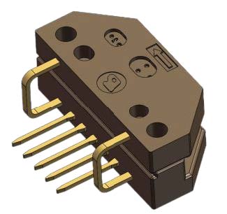
RS9100 2 Channel Optical Incremental Encoder Module
Details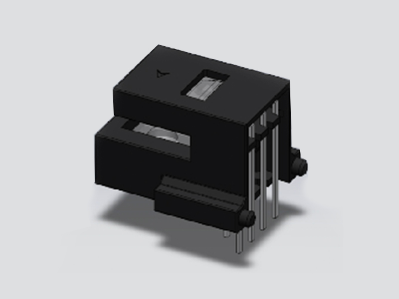
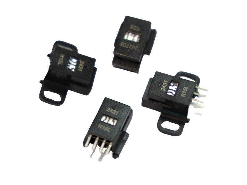
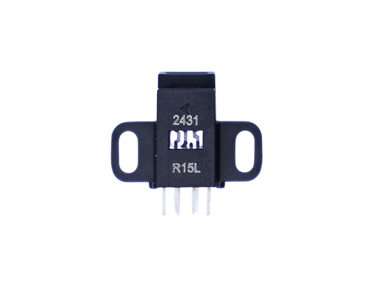
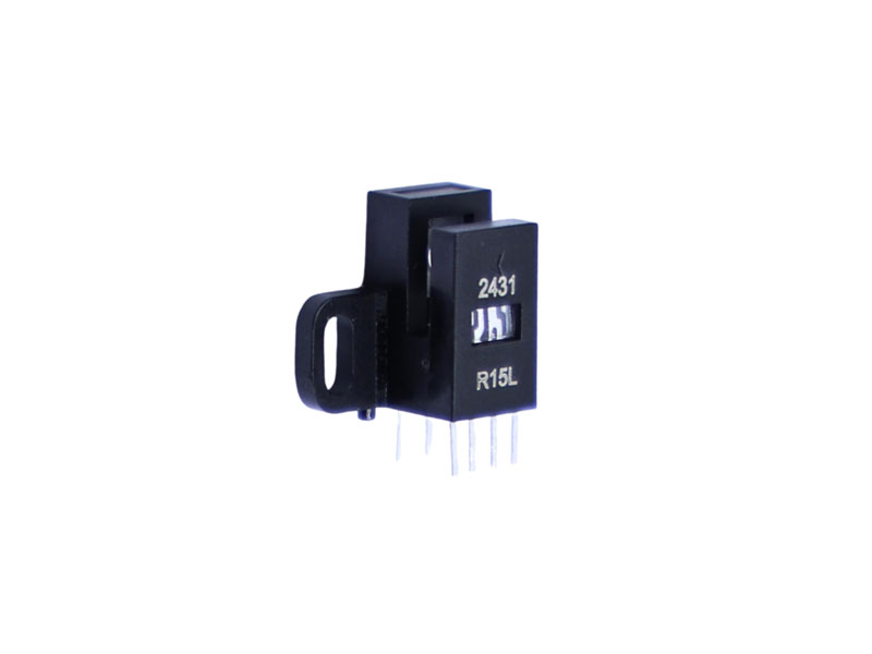
RK_L Optical Encoder Module Kit
DetailsThe EPOCH RK optical encoder kit is a high-performance, low-cost, two-channel optical incremental encoder module in a compact C-shaped plastic package. Designed for rotary and linear position sensing, it delivers up to 600 CPR when matched with a code disc, with a fast 200 kHz response frequency and single 5V supply. The standard encoder kit features TTL-compatible outputs with 2kΩ internal pull-up resistors, and supports both 650nm (red) and 850nm (infrared) light sources for flexible system integration.
Fig.6 — Straight Lead Dimensions Without Mounting Holes
[Upload: RK-Fig6-StraightLead-NoHoles.jpg]

Mechanical drawing — straight lead package without mounting holes (all dimensions in mm)
Fig.7 — Straight Lead Dimensions With Mounting Holes
[Upload: RK-Fig7-StraightLead-WithHoles.jpg]

Mechanical drawing — straight lead package with mounting holes (all dimensions in mm)
Fig.8 — Bent Lead Dimension Without Mounting Holes
[Upload: RK-Fig8-BentLead-NoHoles.jpg]

Mechanical drawing — bent lead package without mounting holes (all dimensions in mm)
Fig.9 — Bent Lead Dimension With Mounting Holes
[Upload: RK-Fig9-BentLead-WithHoles.jpg]

Mechanical drawing — bent lead package with mounting holes (all dimensions in mm)
The EPOCH RK optical encoder kit is a high-performance, low-cost, two-channel optical incremental encoder module. It consists of a highly collimated light source and a detector IC enclosed in a small C-shaped plastic package. When matched with a code disc or codestrip, it provides precise rotary or linear position information. The RK series also supports linear (LPI) encoder configurations with multiple resolution options.
2-channel incremental encoder — Quadrature Aout and Bout outputs with TTL-compatible levels
Up to 600 CPR rotary resolution when paired with a code disc
Linear LPI options: 20, 45, 90, 150, 180, 300, 360 LPI for linear encoder applications
200 kHz response frequency for high-speed motion control feedback
Single 5V supply (4.5V ~ 5.5V) with low power consumption
2kΩ pull-up inside on A and B channel outputs (TTL compatible)
Selectable light source: 650nm (red) or 850nm (infrared)
Wide operating temperature: -20°C ~ +85°C
C-Shape structure — compact plastic package, easy to mount
Multiple mechanical options: straight or bent leads, with or without mounting holes
Typical applications of the RK C-shape optical encoder kit include printers, plotters, copiers, office automation equipment, and industrial automation equipment. The standard encoder kit is also well-suited for servo motor position feedback and general motion control systems requiring reliable 2-channel quadrature output.
| Parameter | Specification |
|---|---|
| Technology | Optical incremental encoder module, C-shape plastic package |
| Output Signals | 2-channel (Aout, Bout) — TTL compatible, 2kΩ pull-up inside |
| Resolution (Rotary) | Up to 600 CPR (matched with code disc) |
| Linear LPI Options | 20, 45, 90, 150, 180, 300, 360 LPI |
| Supply Voltage | 4.5V ~ 5.5V (single 5V) |
| Response Frequency | 200 kHz |
| Operating Temperature | -20°C ~ +85°C |
| Storage Temperature | -40°C ~ +85°C |
| Light Source | 650nm (red) or 850nm (infrared) selectable |
| Parameter | Symbol | Rating |
|---|---|---|
| Storage Temperature | Ts | -40 ~ +85 °C |
| Operating Temperature | TA | -20 ~ +85 °C |
| Supply Voltage | Vcc | -0.5 ~ 7 V |
| Soldering Temperature | — | ≤260 °C (t ≤ 5 s) |
| Response Frequency | f | 200 KHz |
| Reverse Voltage | Vr | 5 V |
| Forward Current (650nm) | If | 30 mA |
| Forward Current (850nm) | If | 70 mA |
Under Recommended Operating Range, Typical at 25 °C
| Parameter | Symbol | Min. | Typ. | Max. | Unit | Condition |
|---|---|---|---|---|---|---|
| Light Source (650nm) Forward Voltage | Vf | 1.8 | 2.0 | 2.3 | V | If = 20 mA |
| Light Source (850nm) Forward Voltage | Vf | 1.4 | — | 1.9 | V | If = 20 mA |
| Light Source (650nm) Wavelength | λp | 650 | — | 660 | nm | If = 20 mA |
| Light Source (850nm) Wavelength | λp | 840 | — | 860 | nm | If = 20 mA |
| Supply Current | Icc | — | 10 | 15 | mA | If = 20 mA |
| Low Level Output Voltage | VOL | — | 0.2 | 0.4 | V | 2kΩ pull-up |
| High Level Output Voltage | VOH | 2.4 | 4.5 | — | V | 2kΩ pull-up |
| A/B Rise Time | tr | — | 160 | — | ns | 2kΩ, CL = 8 pF |
| A/B Fall Time | tf | — | 20 | — | ns | 2kΩ, CL = 8 pF |
| AB Duty Ratio | Dt | 40 | 50 | 60 | % | — |
| A/B Phase Difference | θ | 60 | 90 | 120 | °e | — |
Fig.1 — 650nm Forward Voltage And Forward Current
[Upload: RK-Fig1-650nm-IV-Graph.jpg]

I-V Graph — Forward Voltage (V) vs Forward Current (mA) for 650nm light source
Fig.2 — 650nm Forward Current And Relative Luminous Intensity
[Upload: RK-Fig2-650nm-LI-Graph.jpg]

L-I Graph — Forward Current (mA) vs Relative Luminous Intensity for 650nm light source
Fig.3 — 850nm Forward Voltage And Forward Current
[Upload: RK-Fig3-850nm-IV-Graph.jpg]

I-V Graph — Forward Voltage (V) vs Forward Current (mA) for 850nm light source
Fig.4 — 850nm Forward Current And Relative Luminous Intensity
[Upload: RK-Fig4-850nm-LI-Graph.jpg]

L-I Graph — Forward Current (mA) vs Relative Luminous Intensity for 850nm light source
| VF (V) | 1.5 | 1.6 | 1.7 | 1.8 | 1.9 | 2.0 | 2.1 | 2.2 | 2.3 | 2.4 | 2.5 |
|---|---|---|---|---|---|---|---|---|---|---|---|
| IF (mA) | 1.0 | 1.0 | 1.1 | 1.2 | 3.0 | 7.0 | 12.0 | 18.0 | 24.0 | 29.0 | 30.0 |
I-V reference data — applicable to both 650nm and 850nm light sources (typical values at 25 °C)
Fig.5 — A/B Output Waveform Diagram
[Upload: RK-Fig5-AB-Output-Waveform.jpg]

Quadrature Aout and Bout waveform timing diagram showing 90° electrical phase shift between channels
| Pin Name | Function | Direction |
|---|---|---|
| An | Positive pole of light source (240Ω current limiting resistor recommended, VCC=5V) | Input |
| Ca | Negative pole of light source | Ground |
| Vcc | Power Supply +, 5V | Power |
| Aout | A Channel output, 2kΩ pull-up inside | Output |
| Bout | B Channel output, 2kΩ pull-up inside | Output |
| Gnd | Ground | Ground |
Code Structure: RK [LPI Code] [Lead Type] - [Light Source] [Mounting Holes]
| LPI Code | 02 | 45 | 09 | 15 | 18 | 30 | 36 |
|---|---|---|---|---|---|---|---|
| LPI | 20 | 45 | 90 | 150 | 180 | 300 | 360 |
| Lead Code | 0 | 1 |
|---|---|---|
| Configuration | Straight lead | Bent lead |
| Light Code | 6 | 8 |
|---|---|---|
| Wavelength | 650nm (red) | 850nm (infrared) |
| Holes Code | (omit) | 1 |
|---|---|---|
| Mounting | Without holes | With holes |
Example Ordering Code:
RK300-6
= RK Series · 30=300 LPI · 0=Straight lead · 6=650nm red light source · (omit)=No mounting holes
RK091-81
= RK Series · 09=90 LPI · 1=Bent lead · 8=850nm infrared light source · 1=With mounting holes
The module body is marked with a product label indicating the manufacturing year code and LPI resolution code, as shown below.
Module Printing — Year Code & LPI Marking
[Upload: RK-Module-Printing-Label.jpg]
Product label showing 24XX (year 2024) and RXX (LPI code, e.g. R36 = 360 LPI).
Example codes: 02=20LPI, 09=90LPI, 18=180LPI, 36=360LPI, 45=45LPI, 15=150LPI, 30=300LPI.

For applications requiring a wider supply voltage range (2.7V ~ 5.5V) or additional LPI options (37, 75, 120, 254, 450 LPI), consider the RK_L Series Optical Encoder Kit. The RK_L variant features the same C-shape mechanical design and package with an 850nm infrared light source, but operates at a lower response frequency (60 kHz) and does not include internal 2kΩ pull-up resistors.
A: The RK optical encoder kit provides TTL-compatible 2-channel quadrature outputs (Aout and Bout) with 2kΩ pull-up resistors integrated inside the module, simplifying external circuit design.
A: For rotary applications, the RK incremental encoder kit supports up to 600 CPR when matched with a code disc. For linear encoder configurations, LPI options include 20, 45, 90, 150, 180, 300, and 360 LPI.
A: The RK C-shape optical encoder kit is suitable for printers, plotters, copiers, office automation equipment, industrial automation systems, and servo motor position feedback applications requiring reliable 2-channel incremental position sensing.
Need help selecting the right RK encoder kit?
Contact EPOCH for application-specific guidance and ordering assistance.
Contact Sales →RK series is available in a variety of options, as shown in the table below.


| Item | Description | QTY/Tray | Trays/Carton | G.W | N.W | QTY/Carton | Package Size |
| RK Series | RK Series Optical Encoder Modules | 160 pcs | 10 trays | 1.96 kgs | 0.8 kgs | 1600 pcs | 375*314*165 (mm) |
| 160 pcs | 40 trays | 6.94 kgs | 3.2 kgs | 6400 PCS | 560*270*320 (mm) |
Material Weight Schedule
| Material | Optical Encoder Module | Tray | Carton/Small | Carton/Big |
| Weight | 0.5g/pc | 74g/pc | 420g/pc | 780g/pc |
| QTY/Carton | 1,600pcs / 6,400pcs | 10trays / 40 trays | 1pc | 1pc |
| Weight/Carton | 800g / 3,200g | 740g / 2,960g | 420g | 780g |
| 1,960g/1600pcs | 6,940g/6400pcs |
Discover all the technical specifications by downloading the datasheet today.
| Part Number | Interface |
Dimensions
(mm) |
Resolution Ranges | Resolution Counter |
Communication Frequency |
Working Temperature |
Communication Frequency |
Operation Speeds |
Protection Structure |
Footprint 3D | Datasheet | Sample |
| RZ35A08 | RS485 | Φ35mm | 17~23 Bits | Single/Multi-Turn | Differential output | -20°C-+105°C | 16K | 6000rpm | IP40 |  |
 |
|
| RZ Series | RS485 | Φ48mm | 17~23 Bits | Single/Multi-Turn | Differential output | -20°C-+105°C | 16K | 6000rpm | IP40 | |
|
|
| UZ4409 | RS485 | Φ44mm | 1000-5000CPR | Single/Multi-Turn | Differential output | -20°C-+105°C | 500khz | / | IP40 | |
|
|
| UZ Series | RS485 | Φ48mm | 1000-5000CPR | Single/Multi-Turn | Differential output | -20°C-+105°C | 500khz | / | IP40 | |
|
|
| RS972 | / | / | / | / | / | -40°C to +85°C | / | / | / | |
|
|
| RS970 | / | / | / | / | / | -40°C to +85°C | / | / | / | |
|
|
| RK Series | / | / | / | / | / | -20°C to +85°C | / | / | / | |
|
|
| RS9140 Series | / | / | / | / | / | / | / | / | / | |
|
|
| RS9100 Series | / | / | / | / | / | -40°C to +85°C | / | / | / | |
|
|
| RS971 | / | / | / | / | / | -40°C to +85°C | / | / | / | |
|
|
| RK Series | / | / | / | / | / | -20°C to +85°C | / | / | / | |
|
|
| RF28 | / | / | / | Single/Multi-Turn | / | -40 °C ~+85 °C | / | / | / | |
|
|
| RT28 | / | / | / | Single/Multi-Turn | / | -40 °C ~+85 °C | / | / | / | |
|
|
| RF20 | / | / | / | Single/Multi-Turn | / | -40 °C ~+85 °C | / | / | / | |
|
|
| RR28 | / | / | / | Single/Multi-Turn | / | -40 °C ~+85 °C | / | / | / | |
|
|
| RS5 | / | / | / | Single/Multi-Turn | / | / | / | / | / | |
|
|
| RSG35 | RS485 | / | 17-23 Bits | Single/Multi-Turn | ≤16K | -20 ℃ ~+105 ℃ | 16K | 6000rpm | IP40 | |
|
|
| RSU3506 | RS485 | / | 17-24 Bits | Single/Multi-Turn | ≤16K | -20 ℃ ~+105 ℃ | 16K | 6000rpm | IP40 | |
|
|
| MS Series | / | / | 17 Bits | Single/Multi-Turn | ≤16K | -10℃~105℃ | 16K | ≤6000rpm | / | |
|
|
| RZ1337A | RS485 | / | 25 Bits | Single/Multi-Turn | ≤16K | -20°C-+105°C | 16K | 12000rpm | IP40 | |
|
|
| RZ7810 | / | / | / | / | / | / | / | / | / | |
|
|
| RS Series | RS485 | / | 17~23 Bits | Single/Multi-Turn | ≤16K | -20°C-+105°C | 16K | 6000rpm | IP40 | |
|
Essential for Precision and Reliability in Medical Equipment

Improve Automation and Efficiency in Various Robotic Applications

Improve the Efficiency and Reliability of Automation Systems
Accurate Feedback on Position and Speed