

 Integrated Magnetic Power Module
Buck (Step-Down)-Low Voltage
Buck (Step-Down)-Medium Voltage
Boost (Step-Up)
DC-DC Power Modules
Integrated Magnetic Power Module
Buck (Step-Down)-Low Voltage
Buck (Step-Down)-Medium Voltage
Boost (Step-Up)
DC-DC Power Modules
 Magnetically Integrated Power Module (SiP)
Buck (Step-Down)-Multiple Outputs
Buck (Step-Down)
Boost (Step-Up)
Magnetically Integrated Power Module (SiP)
Buck (Step-Down)-Multiple Outputs
Buck (Step-Down)
Boost (Step-Up)
 Customized DC-DC Converters
Tailored Power Modules: Precision Solutions for Your Unique Needs.
Contact Us Today to Discuss Your Project!
DC-DC Power Modules
Customized DC-DC Converters Explore DC-DC ConvertersEncoder Products
Explore Rotary Encoder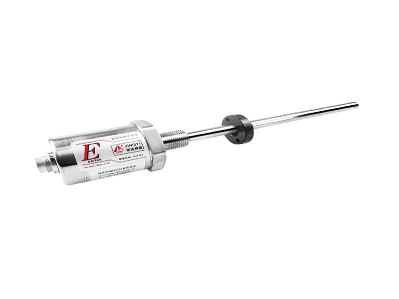
EJ Seris Analog Output Displacement Sensor
Details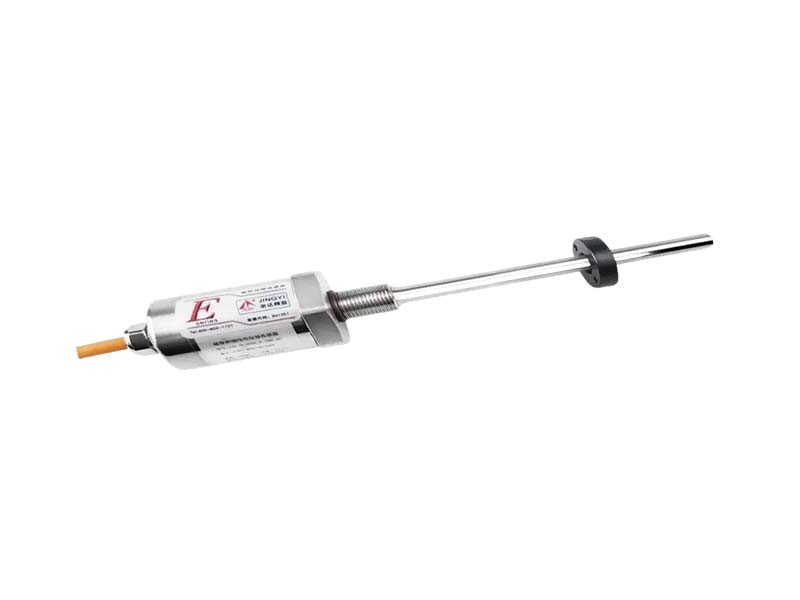
EJ Modbus Output Displacement Sensor
Details
EJ Magnetostrictive Displacement Sensor ( SSI Output )
DetailsProgramming Tools Selection
DetailsMagnet Rings and Floating Balls Selection
Details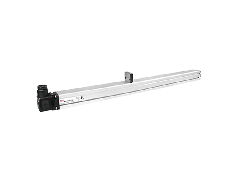
ED Analog Output Displacement Sensor
Details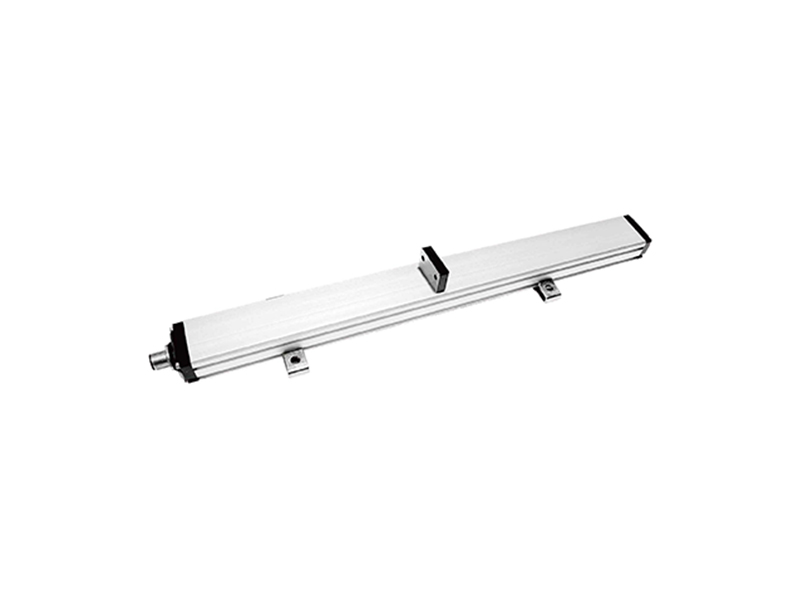
EP Analog Magnetostrictive Displacement Sensor
Details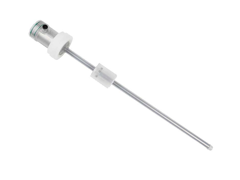
ESC Analog Output Displacement Sensor
Details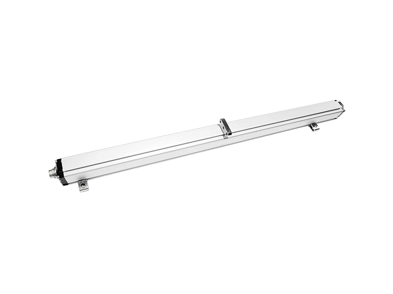
HP Analog Output Displacement Sensor
Details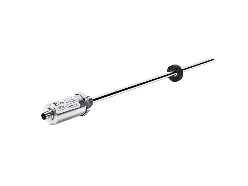
ES Series Magnetostrictive Displacement Sensor
Details
ES Modbus Series Magnetostrictive Displacement Sensor
Details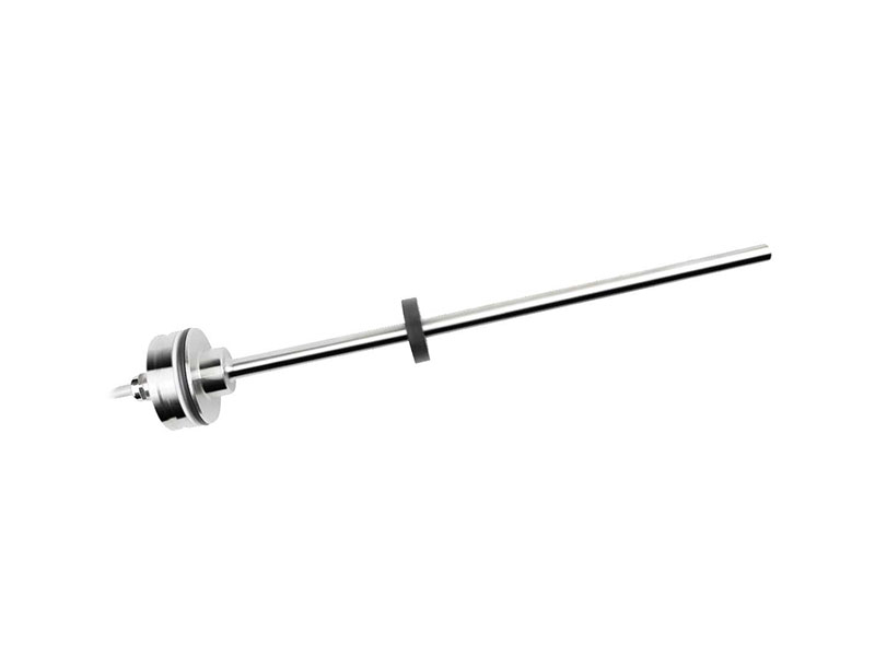
MH Analog Magnetostrictive Displacement Sensor
Details
MH CANopen Displacement Sensor
Details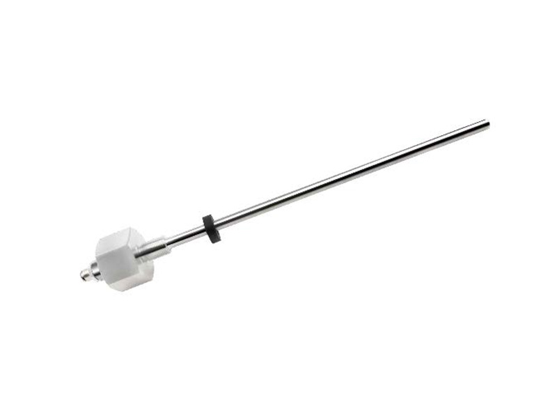
MHA Analog Magnetostrictive Displacement Sensor
Details
MHA CANopen Magnetostrictive Displacement Sensor
Details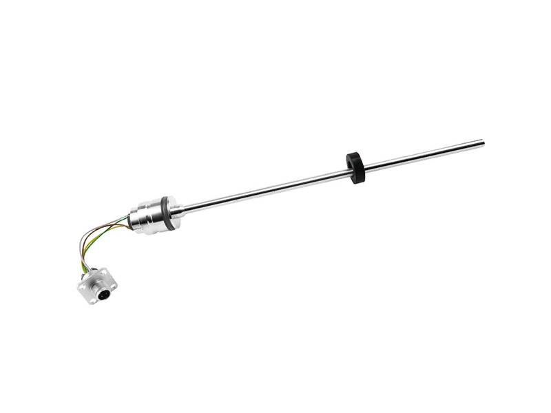
MI Analog Magnetostrictive Displacement Sensor
Details
MI-CANopen Magnetostrictive Displacement Sensor
Details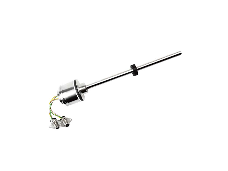
MT-Analog Magnetostrictive Displacement Sensor
Details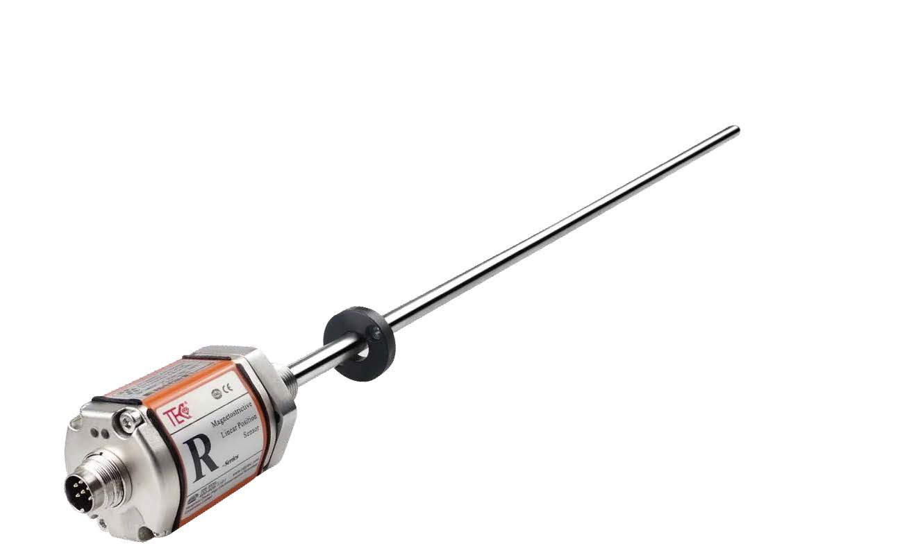
RH/RP Analog Output Magnetostrictive Displacement Sensor
Details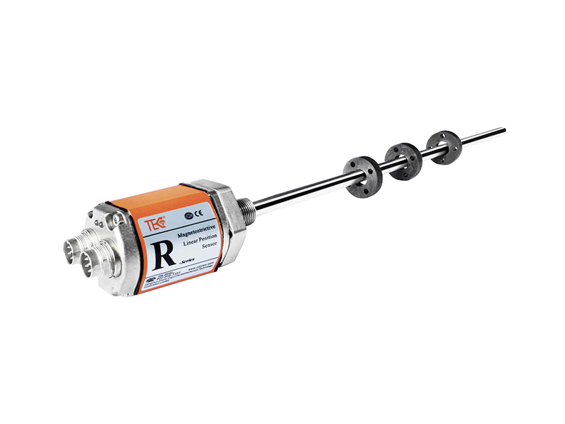
RH/RP CANBus Output Magnetostrictive Displacement Sensor
Details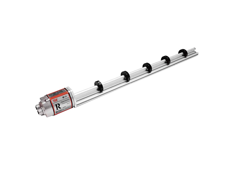
RH-P EtherCAT Output Magnetostrictive Displacement Sensor
Details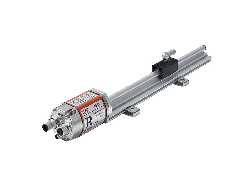
RH(P) Profibus-DP Output Magnetostrictive Displacement Sensor
Details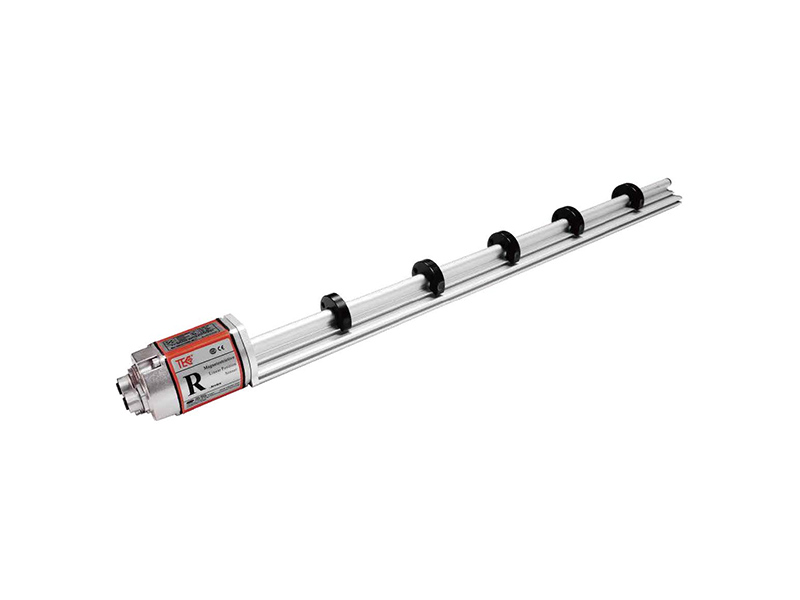
RH(P) Profinet Output Magnetostrictive Displacement Sensor
Details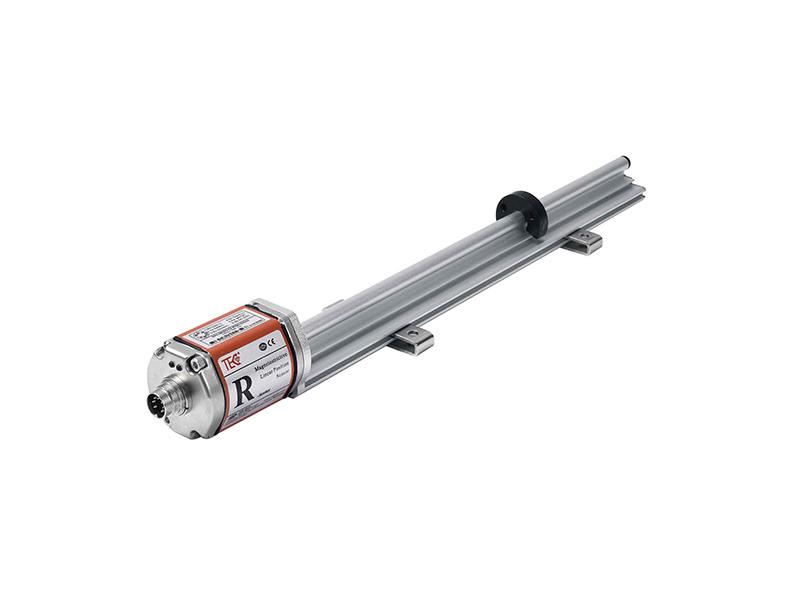
RH(P) SSI Output Magnetostrictive Displacement Sensor
Details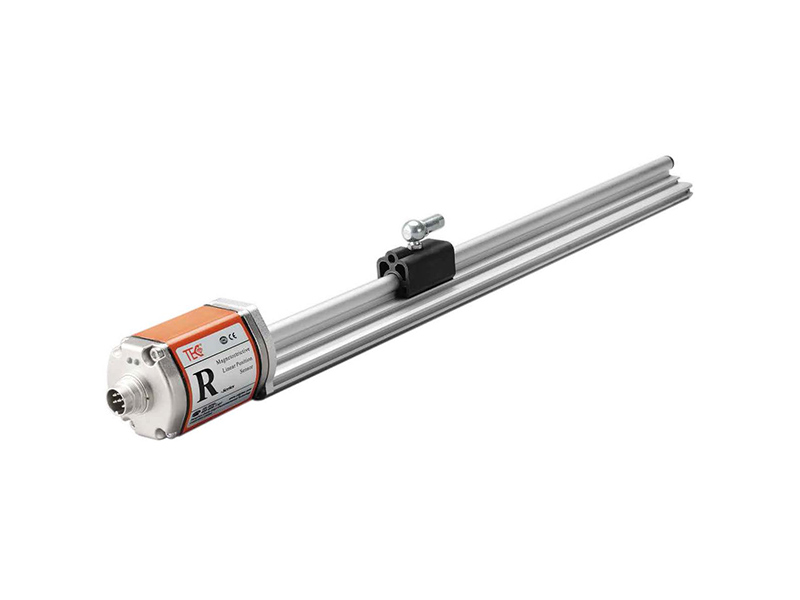
RH(P) Start-Stop Output Magnetostrictive Displacement Sensor
Details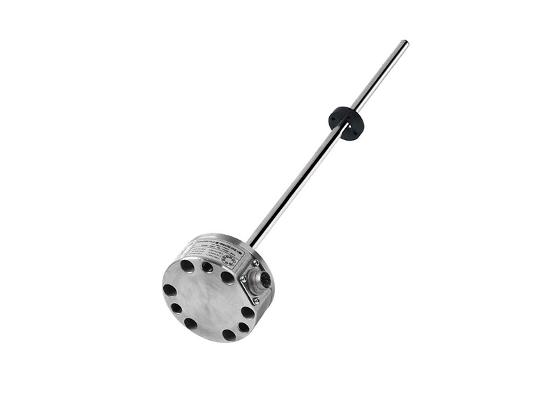
RB Flat Magnetostrictive Position Sensor
Details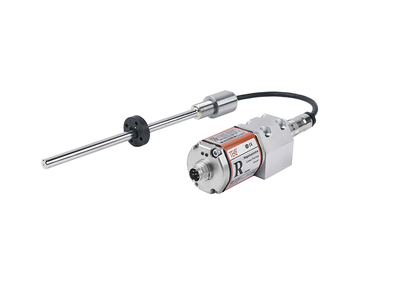
RD Split Magnetostrictive Displacement Sensor
Details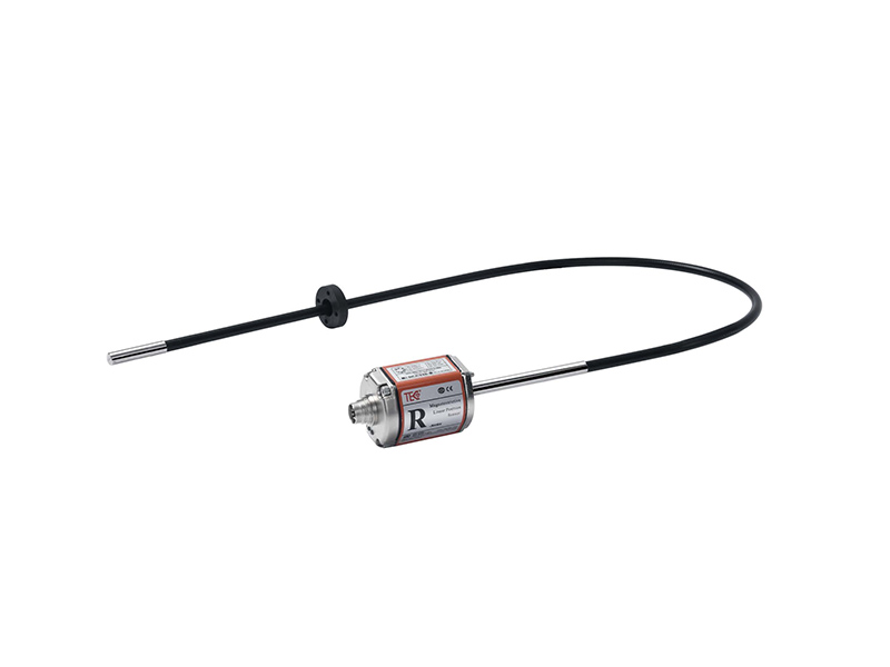
RF Flexible Outer Tube Magnetostrictive Displacement Sensor
Details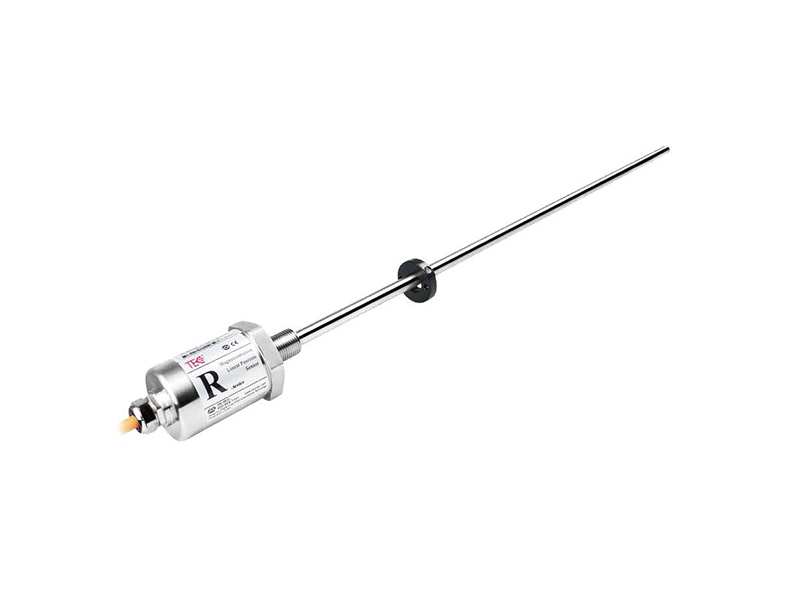
RS Waterproof Magnetostrictive Displacement Sensor
DetailsMagnet Rings and Floating Balls Selection2
DetailsConnector Selection2
DetailsCables Selection2
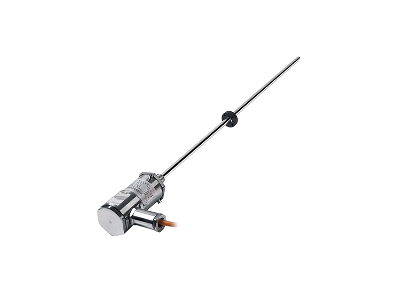
DetailsExplosion-proof and flameproof design certified to ExdⅡBT6 standard ensures safe operation in hazardous environments.
Non-contact, wear-free magnetostrictive technology delivers absolute linear position measurement with long service life.
Robust IP67-rated 304/316L stainless steel construction withstands harsh conditions, including high pressure up to 35 MPa continuous and 70 MPa peak.
Multiple output interfaces available: analog (16-bit D/A), SSI, and CANopen for flexible integration into industrial control systems.
High precision with resolution down to 1 µm, excellent repeatability (<±0.001% FS), and fast update rates (up to 1 kHz) for accurate real-time monitoring.
| ||||
| Measurement data | Position magnet ring | |||
| Stroke length | 25~5500 mm,customized according to customer needs | |||
| Number of measurements | 1 | |||
| |
| Interface | Analog、SSI、CANopen |
| Resolution | Analog:16-bit D/A or 0.0015% of full scale (min. 1μm) Bital quantity:0.5 / 1 / 2 / 5 / 10 / 20 / 40 / 50 / 100 μm |
| Nonlinearity | < ± 0.01% of full scale, Min. ± 50μm |
| Repetition accuracy | < ± 0.001% of full scale, Min. ± 1μm |
Hysteresis | <10μm |
Update time | 1KHz(range≤1m) 500Hz(1m<range≤2m) 250Hz(2m<range≤3m),customizable |
Temperature coefficient | <30ppm/℃ |
| |
| Magnet ring velocity | Arbitrary |
| Protection level | IP67 |
| Operating temperature | -40℃ ~ +85℃ |
| Humidity/dew point | The humidity is 90, and dew cannot be condensed |
| Shock index | GB/T2423.5 100g ( 6ms ) |
| Vibration index | GB/T2423.10 20g/10~2000Hz |
| EMC test | GB/T17626.2/3/4/6/8,Grade 4/3/4/3/3,Class A, CE Certification |
Certified ExdⅡBT6 | Comply with GB3836.1-2010 and GB3836.2-2010 standards Temperature range: T6 (85℃ surface) |
|
| ||
| Input voltage | +24Vdc±20% | Electronic bin | 304 stainless steel |
| operating current | <90mA( varying with range) | Measuring rod | 304/316 L stainless steel |
| Polarity protection | Max.-30Vdc | Outer tube pressure | 35MPa (continuous)/70MPa (peak) or 350ba ( continuous)/700ba (peak) |
| Overpressure protection | Max.36Vdc | Position magnet | Standard Magnet ring and various magnet rings |
| Insulation resistance | >10MΩ | Mounting thread form | M18×1.5、 M20×1.5、3/4"-16UNF-3A (customizable) |
| Insulation strength | 500V | Installation direction | Any direction |
| Cable outlet mode | Special cable outlet(flameproof cable lead-in device) | ||
Installation and Use Instructions
Dimensions of FBGB explosion-proof sensors
FBGB series explosion-proof shell sensor is an explosion-proof structure composed of shell, electronic bin, sensor and lead-in device. It is designed for cylinder built-in installation under harsh environment. The working pressure is 35MPa continuous, flexible and simple installation mode.
The Mounting thread form M18×1.5 or M20×1.5 or inch 3/4”-16UNF-3A.

Wiring Mode
|
| |||
Cable color 1* | Cable color 2* | Pin/wire function definition | Cable color3* | Pin/wire function definition |
| Blue | Grey | No.1 Magnet position signal(+) | Yellow | Current output |
| Green | Pink | Position signal of No.1 Magnet(-) | Grey | 0Vdc(Current/Voltage Loop) |
| Yellow | Yellow | Reservation | Pink | Reservation |
| White | Green | Reservation | -- | Reservation |
| Red | Brown | +24Vdc power supply (-20%~+20%) | Green | 0...10V |
| Black | White | 0 Vdc(power supply circuit) | Blue | 0 Vdc(power supply circuit) |
| Note: * Cable color 1: Cable PUR sheath, orange,-20-90℃ * Cable color 2/3: Cable PVC sheath, orange,-20-105℃ | Brown | +24Vdc power supply (-20%~+20%) | ||
| White | Reservation | |||
|
| |||
Cable color 1* | Cable color 2* | Pin/wire function definition | Cable color3* | Pin/wire function definition |
| White | Grey | Data(-) | Yellow | Clock(+) |
| Yellow | Pink | Data(+) | Grey | Data(+) |
| Blue | Yellow | Clock(+) | Pink | Clock(-) |
| Green | Green | Clock(-) | - | Reservation |
| Red | Brown | +24Vdc power supply (-20%~+20%) | Green | Data(-) |
| Black | White | 0 Vdc | Blue | 0 Vdc(power supply circuit) |
| - | - | Do not connect | Brown | +24Vdc power supply (-20%~+20%) |
Note: * Cable color 1: Cable PUR sheath, orange,-20-90℃ * Cable color 2/3: Cable PVC sheath, orange,-20-105℃ | White | Reservation | ||
| |
| Cable color | Pin/wire function definition |
| Green | CAN (-) |
| Yellow | CAN (+) |
| - | Do not connect |
| - | Do not connect |
| Brown | +24Vdc power supply(-20%~+20%) |
| White | 0 Vdc(power supply circuit) |
Built-in installation instruction of RH pressure-resistant rod sensor

RH Pressure resistance rod sensor installation precautions
Cylinder installing — Pressure tube enclosed transducer (RH) usually has built-in cylinder installing, mounting thread form include: M18 x 1.5, M20 x 1.5, 3/4”-16UNF-3A. Before installation, make sure that the cylinder has been processed according to the correct size given in the atlas.
Mechanical installation — Sensor installation position and direction are not required, but must ensure that the installation is firm and reliable.
The position magnet is installed on the moving part to be measured and keeps a proper distance from the measuring rod.
Outdoor use — when the sensor is used outdoors, it must be equipped with protective devices to prevent rainwater from immersing into the
electronic compartment along cables or connectors in case of rain. The protective cover must consider the water outlet to prevent water accumu-lation.
Position magnet — In order to ensure the accuracy of measurement, the installing bracket of position magnet must be made of non-magnetic materials, such as screws, magnetic insulation gaskets, etc.
Precautions: The sensor is magnetic sensitive equipment, which must keep away from the interference of external strong magnetic field.
The stability and accuracy of power supply should also be considered when measuring with high precision. In use, it is also necessary to prevent the electronic bin from being impacted by foreign objects.
External installation guide of RH pressure-resistant rod sensor
When mounted horizontally, longer sensors (measuring ranges greater than 1m) must be mechanically supported (made of Non-magnetically permeable material).

Installation Instruction
Size and Installation Guidance of RP Aluminum profile Sensor
RP Series Aluminum profile provides a flexible and simple installation. In general, the sensor can be installed on the machine surface with mounting clamps.

Position measurements are achieved using two types of magnets:
1、 The slider magnet moves along the guide rail of the aluminum profile shell, and the moving part is connected with the slider magnet through a connector bearing;
2、The sector magnet is directly installed on the moving part and moves near the surface of the profile, with a gap of 3mm (±1mm).
3、The square magnet is directly installed on the moving part and moves near the surface of the profile, with a gap of 3mm (±2mm).

The integrated LEDs (red or green) provide the basic status feedback and troubleshooting function of the sensor.


| Item | Description | Reel/Tray | Pcs/Roll | G.W | N.W | QTY/Carton | Package Size |
| FBGB Explosion-Proof Seris | FBGB Explosion-Proof Magnetostrictive Displacement Sensor 25~5500 mm stroke Analog、SSI、CANopen Interface -40℃ ~ +85℃ Operating temperature IP67 | -kgs | -kgs | -pcs | -mm |
Discover all the technical specifications by downloading the datasheet today.
| Model | Effective Stroke | Interface | Voltage | Nonlinearity | Repeatability | Updated on | Protection Grade |
Operation Temperature (℃) |
Material | Shock| Pressure | Datasheet | Sample |
 |
||||||||||||
|
||||||||||||
|
||||||||||||
|
||||||||||||
| RS Waterproof Seris | 50mm~5500mm | Analog、SSI、CANopen、Start/Stop | +24Vdc±20% | < ± 0.01% of full scale, Min. ±50μm | < ± 0.001% of full scale, Min. ± 1μm | 1KHz(range≤1m) 500Hz(1m<range≤2m) 250Hz(2m<range≤3m),customizable | IP68 | -40℃ ~ +105℃ | 304 stainless steel | GB/T2423.5 100g(6ms) | |
|
| RF Flexible Seris | 500~7620mm,Up to 23 meters | Analog、SSI、CANopen、Profibus-DP、Start-Stop、Profinet、EtherCAT | +24Vdc±20% | < ± 0.01% of full scale, Min. ± 50μm | < ± 0.001% of full scale, Min. ± 1μm | 1KHz(range≤1m) 500Hz(1m<range≤2m) 250Hz(2m<range≤3m),customizable | IP65 / IP67 | -40℃ ~ +85℃ | Aluminum alloy | GB/T2423.5 100g(6ms) | |
|
| RD Split Seris | 25~5500 mm | Analog、SSI、CANopen、Profibus-DP、Start-Stop、Profinet、EtherCAT | +24Vdc±20% | < ± 0.01% of full scale, Min. ± 50μm | < ± 0.001% of full scale, Min. ± 1μm | 1KHz(range≤1m) 500Hz(1m<range≤2m) 250Hz(2m<range≤3m),customizable | IP68 | -40℃ ~ +125℃ | 304 stainless steel | GB/T2423.5 100g(6ms) | |
|
| RB Flat Seris | 50~5500 mm | Analog、SSI、CANopen | +24Vdc±20% | < ± 0.01% of full scale, Min. ± 50μm | < ± 0.001% of full scale, Min. ± 1μm | 1KHz(range≤1m) 500Hz(1m<range≤2m) 250Hz(2m<range≤3m),customizable | IP67/ IP65 | -40℃ ~ +105℃ | 304 stainless steel | GB/T2423.5 100g(6ms) | |
|
| FBGB Explosion-Proof Seris | 25~5500 mm | Analog、SSI、CANopen | +24Vdc±20% | < ± 0.01% of full scale, Min. ± 50μm | < ± 0.001% of full scale, Min. ± 1μm | 1KHz(range≤1m) 500Hz(1m<range≤2m) 250Hz(2m<range≤3m),customizable | IP67 | -40℃ ~ +105℃ | 304 stainless steel | GB/T2423.5 100g(6ms) | |
|
| RH(P) Start-Stop Output Seris | 25~5500 mm | / | +24Vdc±20% | < 0.01% full-scale taxi, minimum 50μm | / | 1KHz(range≤1m) 500Hz(1m<range≤2m) 250Hz(2m<range≤3m),customizable | IP67/ IP65 | -40℃ ~ +105℃ | 304 stainless steel | GB/T2423.5 100g(6ms) | |
|
| RH(P) SSI Output Seris | 25~5500 mm | SSI Synchronous Serial Interface | +24Vdc±20% | <±0.01% of full scale, minimum ±50μm | <±0.001% of full scale, minimum ±1μm | 1KHz(range≤1m) 500Hz(1m<range≤2m) 250Hz(2m<range≤3m),customizable | IP67/ IP65 | -40℃ ~ +85℃ | 304 stainless steel | GB/T2423.5 100g(6ms) | |
|
| RH(P) Profinet Output Seris | 25~5500 mm | Profinet IO RT | +24Vdc±20% | < ±0.01% of full scale, minimum ±50μm | < 0.001% for full-scale taxis, minimum ±1μm | 1KHz(range≤1m) 500Hz(1m<range≤2m) 250Hz(2m<range≤3m),customizable | IP67/ IP65 | -40℃ ~ +85℃ | 304 stainless steel | GB/T2423.5 100g(6ms) | |
|
| RH(P) Profibus-DP Seris | 25~5500 mm | Profibus-DP System,ISO74498 | +24Vdc±20% | <±0.01% of full scale, minimum ±50μm | <±0.001% of full scale, minimum ±1μm | 1KHz(range≤1m) 500Hz(1m<range≤2m) 250Hz(2m<range≤3m),customizable | IP67/ IP65 | -40℃ ~ +85℃ | 304 stainless steel | GB/T2423.5 100g(6ms) | |
|
| RH-P EtherCAT Seris | 25~5500 mm | EhterCAT Ethernet Control Automation Technology | +24Vdc±20% | <±0.01% of full scale, minimum 50μm | <±0.001% of full scale, minimum ±1μm | ≥0.25ms,depending on the measuring stroke | IP67/ IP65 | -40℃ ~ +85℃ | 304 stainless steel | GB/T2423.5 100g(6ms) | |
|
| RH/RP CANBus Seris | 25~5500 mm | CANBus System Protocol, IS0DIS11898 | +24Vdc±20% | < 0 .01% full-scale taxi, minimum 50μm | <±0.001% of full scale, minimum ±1μm | 1KHz( range ≤1m)500Hz(1m< range ≤2m) 250Hz(2m< range ≤3m),customizable | IP67/ IP65 | -40℃ ~ +85℃ | 304 stainless steel | GB/T2423.5 100g(6ms) | |
|
| RH/RP Analog Seris | 25~5500 mm | / | 0 ~ 10Vdc or 0~5Vdc(min load resistance ≥10K) | <±0.01% of full scale, min±50um | <±0.001% of full scale, min ±1um | 1KHz (range ≤ 1m), 500Hz (1m < range ≤ 2m), 333Hz (2m < range ≤ 3m), customizable | IP67 | -40℃ ~ +85℃ | 304L stainless steel | GB/T2423.5 100g(6ms) | |
|
| MT Analog Seris | 50~2500 mm | CAN bus ISO DIS 11898, CANopen complies with CIA DS-301V3.0, Sensor Specification DS-406V3.1 | 8~ 32Vdc | ±0.1mm(≤250mm)or 0.04%F.S(>250mm) | ±0.1mm | 2ms | IP67 | -40℃ ~ +105℃ | 304L stainless steel | GB/T2423.5 100g(11ms) | |
|
| MI CANopen Seris | 50~2500 mm | CAN bus ISO DIS 11898, CANopen complies with CIA DS-301V3.0, Sensor Specification DS-406V3.1 | 8~ 32Vdc | ±0.1mm(≤250mm)or 0.04%F.S(>250mm) | ±0.1mm | 2ms | IP67 | -40℃ ~ +105℃ | 304L stainless steel | GB/T2423.5 100g(11ms) | |
|
| MI Analog Seris | 50~2500 mm | 4 ~ 20mA(load resistance≤250Ω) | 0.5 ~ 4.5Vdc or 0.25~4.75Vdc | ±0.1mm(≤250mm)or 0.04%F.S(>250mm) | ±0.1mm | 2ms | IP67 | -40℃ ~ +105℃ | 304L stainless steel | GB/T2423.5 100g(11ms) | |
|
| MHA CANopen Seris | 50~2500 mm | CANbus ISO DIS 11898, CANopen complies with CIA DS-301V3.0, Sensor Specification DS-406V3.1 | / | ±0.1mm(≤250mm)or 0.04%F.S(>250mm) | ±0.1mm | 2ms | IP67 | -40℃ ~ +105℃ | 304L stainless steel | GB/T2423.5 100g(11ms) | |
|
| MHA Analog Seris | 50~2500 mm | 4 ~ 20mA(load resistance≤250Ω) | 0.5 ~ 4.5Vdc or 0.25~4.75Vdc | ±0.1mm(≤250mm)or 0.04%F.S(>250mm) | ±0.1mm | 2ms | IP67 | -40℃ ~ +105℃ | 304L stainless steel | GB/T2423.5 100g(11ms) | |
|
| MH CANopen Seris | 50~2500 mm | CAN bus ISODIS11898, CANopen conforms to CIA DS-301V3.0, sensor specification DS-406V3.1 | 9~ 32Vdc | ±0.1mm(≤250mm)or 0.04%F.S(>250mm) | ±0.1mm | 2ms | IP67 | -40℃ ~ +105℃ | 304L | GB/T2423.5 100g(11ms) | |
|
| MH Analog Seris | 50~2500 mm | / | 9~ 32Vdc | ±0.1mm(≤250mm)or 0.04%F.S(>250mm) | ±0.1mm | 2ms | IP67 | -40℃ ~ +105℃ | 304L | GB/T2423.5 100g(11ms) | |
|
| ES Modbus Seris | 25–3500 mm | Modbus RTU protocol | 9~ 30Vdc | Minimum ± 50um or <0.01%.F.S | Minimum ± 10um or <0.001%.F.S | Default 20ms | IP67 | -40°C ~ +75°C | 304L/316L | GB/T2423.5 50g(6ms) | |
|
| ES Analog Seris | 25–5500 mm | 4-20mA or 0-20mA | 0~10Vdc or 0~5Vdc | 0.05% F.S | Same resolution | lms (four wire system)/ 100 ms (two wire system) | IP67 | -40°C ~ +75°C | 304L / 316L stainless steel | GB/T2423.5 50g(6ms)/ 35MPA / 70MPA ( peak | |
|
| HP Analog Seris | 25–2500 mm | 4-20mA or 20-4mA | 0~10Vdc or 0~5Vdc | <0.02% of full scale | <0.005% of full scale | lms ( range < lm ) | IP65 | -40°C ~ +85°C | PFA | GB/T2423.5 50g(6ms) | |
|
| ESC Analog Seris | 50–3000 mm | 4-20mA or 20-4mA | 0~10Vdc or 0~5Vdc | 士0.1mm(25~400mm) | <±0.l mm | lms (four wire system)/ 100 ms (two wire system) | IP67 | -40°C ~ +75°C | PFA | GB/T2423.5 50g(6ms) | |
|
| EP Analog Seris | 25-5500 mm | 0-20mA or 4-20mA | 0~10Vdc or 0~5Vdc | 0.05% F.S | < 0.03% of full scale | < 0.005% of full scale | IP65 | -40°C ~ +85°C | Aluminum formed shell | GB/T2423.5 50g(6ms) | |
|
| ED Analog Seris | 50–3000 mm | / | 0–10V/10–0V, signal/ dual | <±0.05% of full scale | <± 0.01% of full scale | 2MS | IP65 | -40°C ~ +75°C | Aluminum Alloy | GB/T2423.5 50g(11ms) , 5 g,10–2000 Hz GB/T2423.10 | |
|
|
||||||||||||
|
||||||||||||
|
||||||||||||
|
||||||||||||
| EJ SSI Output Seris | 25-5500 mm | SSI Synchronous Serial Interface | +24Vdc±20% | <±0.01% of full scale, minimum±50μm | < ± 0.001% of full scale, minimum ± 5μm | / | Cable outlet mode IP68; socket way IP67 | -40℃ ~ +85℃ | 304L | GB/T2423.5 100g(6ms) | |
|
| EJ Modbus Seris | 25-5500 mm | Modbus RTU protocol | 0-10Vdc or 0-5Vdc | Minimum ±50um(or <±0.01%F.S.) | Minimum ±10um(or <±0.001%F.S.) | 10ms | IP67 | -40°C - +75°C | 304L/316L stainless steel | GB/T2423.5 50g ( 6ms ) | |
|
| EJ Analog Seris | 25-5500 mm | 4-20mA or 0-20mA | 0-10Vdc or 0-5Vdc | <+0.02% of full scale | <± 0.001% offull scale | lms | Outgoing line lP68, Socket LP67 | -40°C - +75°C | 304L/316L stainless steel | GB/T2423.5 50g(6ms), 35MPA/70MPA(peak) | |

Essential for Precision and Reliability in Medical Equipment

Improve Automation and Efficiency in Various Robotic Applications

Improve the Efficiency and Reliability of Automation Systems
Accurate Feedback on Position and Speed